
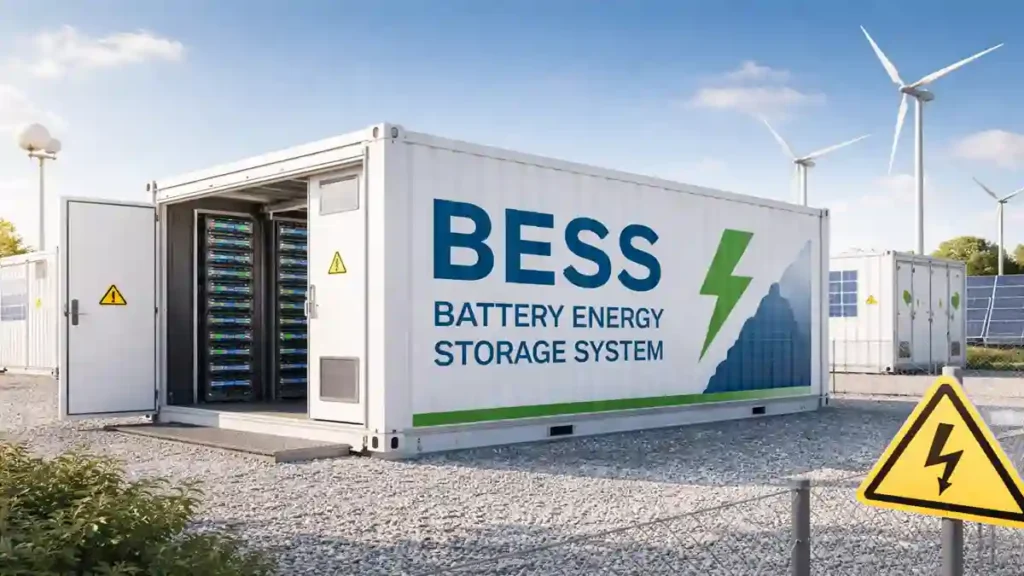
Properly sizing a Battery Energy Storage System (BESS) and solar panel array is the single most critical step in designing a reliable solar installation. Because Lithium-ion LiFePO<sub>4</sub> batteries represent a substantial portion of a solar plant’s initial capital cost, miscalculations carry immediate financial and operational consequences.
Table of Contents
Common BESS & Solar Sizing Mistakes
Confusing Peak Power vs. Continuous Energy: Counting the total watts of your appliances without multiplying by running hours. This leads to batteries that handle the initial load fine but run empty long before expected.
Ignoring Motor Starting Surges (Inrush Current): Failing to account for the temporary 3X–5X power spikes drawn by motorized equipment (like air conditioners or industrial pumps) when they start up.
Underestimating Solar Recharge Capacity: Sizing a large battery bank without enough solar panels to fully recharge it daily alongside running daytime loads.

The Real-World Impact
For Homeowners:
Unexpected Blackouts: Running out of power in the middle of the night due to inaccurate capacity planning.
System Trips: Inverters shutting down or tripping as soon as high-surge appliances (like an AC compressor) kick on.
Premature Battery Failure: Deeply discharging the battery bank beyond its safe Depth of Discharge (DoD) leads to rapid cell degradation and wasted money.
For Industrial Users:
Tripped Production Lines: Instantaneous voltage drops caused by motor inrush currents can halt machinery and ruin manufacturing batches.
Costly Operational Downtime: Unexpected outages halt factory shifts and delay delivery schedules.
Severe Grid Penalties: Exceeding peak demand limits or pulling sudden reactive power spikes during solar dips incurs heavy utility penalty fees.
1. Why Keep a Daytime Buffer Margin?
Under ideal sunlight, solar panels carry 100 % of daytime power demands. However, solar generation fluctuates dynamically throughout the day. Engineers include a 15 % — 25% daytime buffer in battery sizing for three core reasons:
Transient Cloud Cover (Solar Intermittency): When passing clouds obscure the sun, solar panel output drops by 50 % to 80% in seconds. Without a battery buffer ready to fill the temporary deficit, the hybrid inverter trips on overload or experiences severe voltage sag.
Midday Grid Outages during Overcast Weather: If grid power cuts out at 1:00 PM while heavy cloud cover reduces solar yield, the battery must supply the difference to keep appliances or machines running smoothly.
Preventing Rapid Battery Cycling: Without a calculated buffer, the Battery Management System (BMS) continuously switches between brief high-current discharges and aggressive charge cycles as sunlight toggles, accelerating thermal stress and battery degradation.
2. Essential Sizing Inputs & Key Terms
Continuous Load (kW): The steady running power consumed by running equipment.
Inrush / Starting Surge (kW): The brief burst of extra power ( 3X – 5X running power) drawn by motor-driven compressors (air conditioners, industrial pumps) when starting up.
Depth of Discharge (DoD): The safe usable limit of a battery. For Lithium ( LiFePO4 , this is typically 80 % — 90 % . Draining to 0 % degrades cell health.
Peak Sun Hours (PSH): The equivalent daily hours of full sunlight intensity 1,000 W/m2
. Average values range from 4 to 5 PSH.An Aging Buffer (or Capacity Degradation Reserve) is an extra percentage of battery capacity added during the design and sizing phase of an Energy Storage System (BESS) to ensure the system can still meet its target backup requirements at the End of Life (EOL). Without an aging buffer- A battery sized for exactly 10 kWh of required energy on Day 1 will only deliver 8 kWh by Year 8–10. This causes unexpected power outages as the system ages, even if power consumption stays the same.
KEY DATA INPUTS FOR SIZING
Understanding the Load Profile & System Calculations
Sizing a Battery Energy Storage System (BESS) requires evaluating two distinct metrics: Continuous Running Load (power required over time) and Peak Inrush Surge (instantaneous power required to start electric motors).
Below is the complete load profile and system calculation breakdown structured for both residential and commercial applications.

1. Residential System Calculation
A. Load Profile Breakdown
1.5 Ton Inverter AC
Running Power: 1,500 W ( 8 hrs/day => 12,000 Wh)
Peak Starting Surge: 3,500 W (2.3 times inrush factor)
Refrigerator
Running Power: 150 W ( 10 hrs active=> 1,500 Wh )
Peak Starting Surge: 450 W ( 3.0 times inrush factor)
Lighting & Entertainment (TV, LED Bulbs, Fans)
Running Power: 385 W ( 2,560 Wh/day )
Peak Starting Surge: 385 W
TOTAL HOME DEMAND: 2.04 kW Running | 4.34 kW Peak Surge | 16.06 kWh/day
BATTERY CAPACITY & RUNTIME ANALOGY
B. Step-by-Step Sizing Checklist for Battery Calculation
Step 1: Nighttime Outage Energy (6 hrs)
Demand = 2.04 kW X 6 hours = 12.24 kWhStep 2: Daytime Cloud Cover Buffer (1.5 hrs)
Demand = 2.04 kW X 1.5 hours = 3.06 kWhStep 3: Total Required Battery Capacity
Target Energy = 12.24 + 3.06 = 15.30 kWhStep 4: Battery Sizing (with Losses & 10-Yr Aging Cushion)
$$\text{Usable Capacity} = \frac{15.30\text{ kWh}}{0.90\text{ (Inverter Eff)} \times 0.80\text{ (DoD)}} = 21.25\text{ kWh}$$
Final Sized Capacity = 21.25 kWh X 1.20 (Aging Buffer) = 25.50 kWh
C. Solar Panel Calculation Principles
To size solar panels accurately, you must determine how much daily energy (in kWh) the panels need to generate to cover two main tasks:
Direct Daytime Consumption: Powering loads running while the sun is shining.
Battery Replenishment: Pushing enough energy back into the battery bank so it reaches $100\%$ charge before sunset.
Input Data
Daytime Energy Use (6 hrs): 2.04 kW X 6 hours = 12.24 kWh
Battery Energy to Replenish: 15.30 kWh (Solar panels are sized to recharge the energy drawn (15.30 kWh), not the total battery capacity (25.50 kWh). Sizing for the full nameplate capacity would unnecessarily oversize your solar panel array to fill a reserve buffer that is never emptied)
Battery Charging Efficiency: 90 %
Location Peak Sun Hours (PSH): 4.5 hours/day
System Derating Factor: 1.15 (accounts for panel dust, wiring losses, and thermal degradation)
SOLAR ARRAY CALCULATION FORMULA

C1. Step-by-Step Solar Panel Calculation Checklist
1.Calculate Energy Needed for Battery Charging:
Account for charging losses when storing energy into the battery:
Verification: Check if your solar system monitor shows ~17 kWh supplied to the battery bank during daytime charging.
2.Calculate Total Daily Target Generation:
Combine daytime appliance running power and battery charging energy, then apply the loss/derating factor:
Verification: Monitor daily solar yield to confirm it hits ~33.6 kWh on clear sunny days.
3.Calculate Required Solar Panel Size (kWp):
Divide total daily target generation by regional Peak Sun Hours 4.5 PSH :
Verification: Confirm the total wattage sum of all installed panels equals or exceeds 7.47 kWp.
The no. of Solar panels can be found by dividing 7.47 kWp by panel Wp (Watt Power).

D. Step-by-Step Guide: Hybrid Solar Inverter Sizing Checklist
Sizing a hybrid solar inverter isn’t as simple as picking a rating that matches your basic running watts. A proper calculation requires evaluating three distinct operational requirements: Continuous Running Load, Peak Starting Surge (Inrush Current), and Maximum Solar Panel Input.
Below is the exact 3-step engineering process used in our residential case study
Step 1: Calculate the Total Continuous Running Load
List all essential household appliances intended to run simultaneously during a power outage and sum their rated running wattage:
Calculated 2.04 kWh Running Load in Load Profile Breakdown above.
Base Requirement: The inverter must deliver at least 2.04 kW of continuous AC power without overheating.
Step 2: Check for Peak Motor Starting Surges (Inrush Current)
Appliances with electric motors or compressors (like air conditioners, pumps, and refrigerators) draw a brief 2 times to 3 times surge spike for 1 to 3 seconds when starting up from a dead stop.
In above example : it was calculated as 4.34 kW peak Surge in the Load Profile Breakdown.
Surge Requirement: The inverter’s surge rating (typically 1.5 times to 2 times its continuous rating for 5 seconds) must handle at least 4.04 kW to prevent the system from tripping when the air conditioner turns on.

Step 3: Match Inverter Capacity to Solar Panel Input (kWp)
This is where many installers make a critical mistake. While a 5 kW Hybrid Inverter easily handles the 2.04 kW continuous load and 4.04 kW starting surge, we calculated that our rooftop array requires 7.70 kWp of solar panels to meet both daytime household usage and battery recharge demands.
Most 5 kW inverters are limited to a maximum PV input of ~ 5.5 kWp – 6.0 kWp. Connecting a 7.70 kWp panel array would overload the inverter’s MPPT solar charger.
Therefore, the inverter capacity is upgraded to match the solar array capacity:
Executive Inverter Sizing Summary Card
RESIDENTIAL INVERTER SELECTION
Continuous Power Demand: 2.0 kW
Peak Starting Surge Demand: 4.04 kW
Required Solar Panel Input: 7.70 kWp Array.
Selected Hardware: 8 kW Single-Phase Hybrid Solar Inverter (handles 2.04 kW continuous load, 16 kW peak surge, and up to 8 10 kWp PV input).
Golden Formula for Inverter Sizing
Residential Sizing Executive Summary
| Sizing Parameter | Recommended Hardware Specification |
| Continuous Running Power | 2.04 kW |
| Peak Inrush Surge Power | 4.34 kW (AC compressor surge) |
| Calculated Battery Pack | 25.6 kWh |
| Hybrid InverterPCS Sizing | 8 kW Single-Phase Hybrid Inverter |
| Solar Panel Array Sizing | 7.7 kWp |
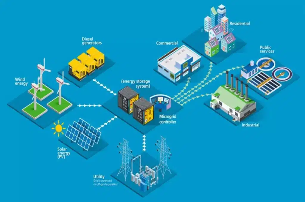
Case Study 2: Commercial / Industrial Calculations
Industrial plants differ from homes in two major ways: they operate large continuous loads ($100+\text{ kW}$) and experience massive starting power spikes (inrush currents) caused by heavy electric motors, pumps, and compressors.
Below is the complete step-by-step sizing breakdown for a light manufacturing facility.
1. Facility Load Profile Breakdown
Refrigeration Compressor 1 (VFD Starter)
Running Power: 30 kW (12 hrs/day → 360 kWh)
Peak Starting Surge: 45 kW (1.5× inrush factor via Variable Frequency Drive)
Refrigeration Compressor 2 (Direct-On-Line Starter)
Running Power: 30 kW (12 hrs/day → 360 kWh)
Peak Starting Surge: 90 kW (3.0× inrush factor from direct motor startup)
Conveyor Systems & Motors (Soft Starters)
Running Power: 30 kW (8 hrs/day → 240 kWh)
Peak Starting Surge: 54 kW (1.8× inrush factor)
Plant Lighting & Facility HVAC
Running Power: 10 kW (12 hrs/day → 120 kWh)
Peak Starting Surge: 10 kW (No starting surge)
TOTAL FACTORY DEMAND
Continuous Running Load: 100 kW
Peak Inrush Surge Demand: 160 kW (70 kW running + 90 kW single-motor surge)
Total Daily Energy Draw: =360 kWh + 360 kWh + 240 kWh +120 kWh= 1,080 kWh/day
2. Industrial Battery Storage Calculation (BESS)
Backup Requirements Profile
Nighttime / Shift Backup: 2 hours of full-load backup during evening power cuts 100 kW x 2 hrs = 200 kWh.
Daytime Cloud Cover & Intermittency Buffer: 1 hour buffer during daytime operations 100 kW x 1 hr = 100 kWh.
1.Calculate Total Net Energy Demand:
Combine nighttime backup energy and daytime cloud buffer energy:
2.Apply BESS Efficiency & Depth of Discharge (DoD):
Adjust for commercial BESS conversion efficiency 92% and safe industrial LFP Depth of Discharge 85%:
3.Apply 10-Year Capacity Aging Buffer:
Add a 15% capacity margin so the system still satisfies the 300 kWh backup target at 10-year End of Life ( 85 % State of Health ):
COMMERCIAL BESS HARDWARE SELECTION
Calculated BESS Demand: 441.1 kWh
Selected Hardware: 500 kWh Outdoor Containerized BESS Rack (High-Voltage 400V/800V DC System)

3. Industrial Solar Panel Array Calculation
Input Data Profile
Daytime Operating Load (6 hrs): 100 kW X 6 hrs = 600 kWh
Net Energy to Replenish in Battery: 300 kWh ( from above calculation).
Location Peak Sun Hours (PSH): 4.8 PSH/day
System Loss Factor: $\mathbf{1.18}$ (18% buffer for heat loss, inverter, and industrial cabling)
1.Calculate Energy Needed for BESS Charging:
Calculate actual energy input required from the solar array to charge the BESS:
2.Calculate Total Daily Target Generation:
Sum daytime operating energy and battery recharge requirements, applying system loss factors:
3.Calculate Required Solar Peak Capacity (kWp):
Divide total daily energy target by industrial location sunlight hours 4.8 PSH
COMMERCIAL SOLAR SELECTION SUMMARY
Calculated Solar Demand: 227.66 kWp
4. COMMERCIAL PCS / INVERTER SELECTION SUMMARY
Continuous Power Capacity: 100 kW
Peak Starting Surge Capacity: 160 kW
Required Solar Capacity: 227.7 kWp
Selected Hardware: 150 kW/ 200 kVA Commercial BESS PCS Unit (Handles 100 kW continuous load, up to 225 kW peak surge for 10 seconds, and pairs with a 230 kWp solar charger).
Industrial inverters are sized in kVA rather than just kW to account for inductive motor power factors (PF 0.75 ). A 150 kW/ 200 kVA unit provides a comfortable 67 % continuous operating margin on the 100 kW base load while delivering up to 225 kW of temporary surge power to absorb direct-on-line motor starting spikes.
Engineering Note: Why Inverter Sizing Uses Apparent Power (kVA) & Power Factor
In commercial and industrial BESS engineering, sizing an inverter based strictly on active power (kW) causes severe operational overloads. Heavy factory equipment (compressors, pumps, motors) draws reactive power alongside active power, reducing the plant's power factor to roughly 0.75 lagging.
To deliver 150 kW of working power under a 0.75 PF, the inverter must support an apparent power rating of:
Apparent Power (kVA) = 150 kW ÷ 0.75 PF = 200 kVA
Furthermore, a 150 kW / 200 kVA PCS delivers up to 225 kW of 10-second surge power (1.5× overload margin), easily absorbing direct-on-line motor starting spikes (up to 160 kW) without tripping the system or dropping grid voltage.
Executive Industrial Sizing Matrix
| Metric / Parameter | Calculated Requirement | Final Selected Hardware |
| Continuous Running Power | 100 kW | 150 kW Commercial PCS Unit |
| Peak Starting Surge | 160 kW (Motor DOL starting) | Handled by 1.5× PCS surge rating |
| Battery Storage Capacity | 300 kWh net; 441.1 kWh (nominal) | 500 kWh Outdoor BESS Container |
| Solar Panel Generation | 1,092.8 kWh/day | 227.7 kWp Array |
Key Takeaways & Precautions for Solar Energy Storage Sizing
Whether designing for a home with a single air conditioner or a light manufacturing facility running heavy industrial motors, accurate load calculation forms the foundation of a successful Battery Energy Storage System (BESS). Balancing continuous power demands with peak starting surges, while incorporating essential buffers for depth of discharge, cloud cover, and long-term battery aging, ensures that your solar BESS delivers uncompromised reliability across its entire 10-to-15-year lifecycle. Skimping on these calculation steps or misinterpreting power factors and inrush currents inevitably leads to premature battery degradation, system overloads, and unexpected blackouts.
To safeguard your investment, strict installation and design precautions must be observed:
Conduct a Comprehensive Site Audit: Never rely on general assumptions. Measure actual peak surge currents using data loggers, evaluate grid voltage stability, and verify power factors before finalizing equipment specifications.
Prioritize Advanced Thermal and Safety Controls: Ensure battery enclosures—whether low-voltage residential racks or high-voltage commercial containerized units—are equipped with certified Battery Management Systems (BMS), active thermal cooling, and automatic fire suppression.
Factor in Real-World Environmental Conditions: Account for local ambient temperature spikes, dust accumulation, and roof orientation loss factors when sizing solar panel arrays to guarantee complete daily battery replenishment.
Partner with Tier-1 Certified Vendors and System Integrators: Select reputable equipment manufacturers and qualified EPC contractors who offer proven tier-1 lithium chemistries ($\text{LiFePO}_4$), comprehensive multi-year warranties, responsive local technical support, and seamless software integration between solar chargers, inverters, and battery management platforms.
A well-calculated BESS engineered alongside a trusted vendor turns energy storage from a risky capital expense into a high-yield, future-proof asset that guarantees energy independence and long-term cost savings.
